KEYPAD INTERFACING WITH PIC
An alphabetic keypad is similar to a numeric keypad, but it provides the complete set of alphabetical letters instead of numbers 0-9.
Synopsis

An alphabetic keypad is similar to a numeric keypad, but it provides the complete set of alphabetical letters instead of numbers 0-9. This article presents a way to interface a keypad with 18F4550 microcontroller to display alphabetical characters on an LCD module. Such kind of systems is commonly used in mobile phones to write an SMS and other texts. It can have further applications in displaying instant messages on other display systems such as LED matrices or other multi-segment displays.

Description

Keypad is organized as a matrix of switches in rows and column. We uses a 4X3 or 4x4 matrix keypad and a 16x2 LCD for displaying the output of keypad. The matrices are actually an interface technique. It can be used to interface inputs like the PC keyboard keys, but also to control multiple outputs like LEDs. According to this technique, the I/O are divided into two sections: the columns and the rows. Here it is a 4 x 4 matrix.


The blue lines are the columns and the red lines the rows. There are 16 knots that the rows and columns intersect. The columns and the rows are NOT in contact. Suppose that we want to make a key matrix. To do this, we will have to connect a button to each knot. The buttons will have a push-to-make contact. When the operator pushes this button, it will connect the column and the row.


The buttons are named with the Column:Row name that they connect. For example, the top-left button is named A1 and the bottom right is named D4.

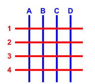
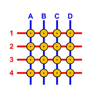
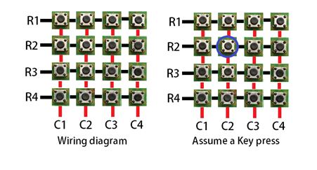
Internal wire connection of keypad

Here, the matrix keypad is wired internally.


From the above circuit you can see that when one of the 16 buttons are pressed, a pair of pins are connected together. We will use this feature to detect the button that was pressed in the following sections.

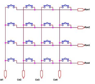
Matrix Keypad Interface Logic

In programming of keypad Interfacing we have two methods:-

• Key Press Detection

• Key Identification

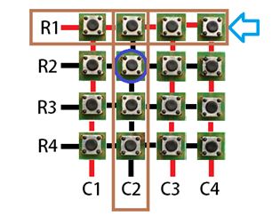
There are two ways by which PIC18F can perform key press detection :-

• Interrupt Method and

• Scanning Method (this method is used in AT89C51 Example)

In PIC18F, the PORTB-Change Interrupt feature can be used to detect the key press using Interrupt and it is specially provided by Mirochip for such interfacing and is much more efficient than scanning method.

Initial setup:

• supply logic 0 (0V or GND) to all 4 keypad row wires or set the row pins as output.

• Supply logic 1 (high voltage) to all 4 keypad coloum wires or set coloums as input.

Initially all switches are assumed to be released. So there is no connection between the rows and columns. When any one of the switches are pressed, the corresponding row and column are connected (short circuited). This will drive that column pin (initially high) low. Using this logic, the button press can be detected. The colors red and black is for logic high and low respectively. Here are the steps involved in determining the key that was pressed.

Step 1:

The first step involved in interfacing the matrix keypad is to write all logic 0’s to the rows and all logic 1’s to the columns. In the image, black line symbolizes logic 0 and red line symbolizes logic 1.

For now let us assume that, the circled key is pressed and see how the key press can be detected by a software routine.


Step 2:

Now the software has to scan the pins connected to columns of the keypad. If it detects a logic 0 in any one of the columns, then a key press was made in that column. This is because the event of the switch press shorts the C2 line with R2. Hence C2 is driven low. Note: color of the lines indicate the logic values they return.


Step 3

Once the column corresponding to the key pressed is located, the next thing that the software has to do is to start writing logic 1’s to the rows sequentially (one after the other) and check if C2 becomes high. The logic is that if a button in that row was pressed, then the value written to that row will be reflected in the corresponding column (C2) as they are short circuited. Note: color of the lines indicate the logic values they return.


Step 4:

The procedure is followed till C2 goes high when logic high is written to a row. In this case, a logic high to the second row will be reflected in the second column. Note: color of the lines indicate the logic values they return.

We already know that the key press happened at column 2. Now we have detected that the key is in row 2. So, the position of the key in the matrix is (2,2). Once this is detected, its up to us to name it or provide it with a task on the event of the key press.

Steps to read a key from the keypad

1. Find the Row first, by selecting each row

2. scan the colum which pressed key is

3 Find the key pressed ,the function findKey() is for this

If we have at least one key pressed, then return from keypadread() will be non zero.

Applications:

• ATM Machine

• Computer,

• Mobile Phone

Proteus design for Keypad interfacing with PIC


Orcad design for Keypad interfacing with PIC


Keypad interfacing with PIC

/*  Name     : main.c
 *  Purpose  : Source code for KEYPAD Interfacing with PIC18F4550.
 *  Author   : Gemicates
 *  Date     : 2017-07-07
 *  Website  : www.gemicates.org
 *  Revision : None
 */

#include <htc.h>                    //Header file for PIC18F4550
#define _XTAL_FREQ 12000000         //12MHZ

/**********CONFIGURATION BITS SETTING**********/
#pragma config FOSC = HSPLL_HS           // Using 20 MHz crystal with PLL
#pragma config PLLDIV = 5                // Divide by 5 to provide the 96 MHz PLL with 4 MHz input
#pragma config PBADEN = OFF
#pragma config CPUDIV = OSC1_PLL2        // Divide 96 MHz PLL output by 2 to get 48 MHz system clock
#pragma config FCMEN = OFF               // Disable Fail-Safe Clock Monitor
#pragma config IESO = OFF                // Disable Oscillator Switchover mode
#pragma config PWRT = OFF                // Disable Power-up timer
#pragma config BOR = OFF                 // Disable Brown-out reset
#pragma config WDT = OFF                 // Disable Watchdog timer
#pragma config MCLRE = ON                // Enable MCLR Enable
#pragma config LVP = OFF                 // Disable low voltage ICSP
#pragma config ICPRT = OFF               // Disable dedicated programming port (only on 44-pin devices)
#pragma config CP0 = OFF                 // Disable Code Protection Bit
/************************************************/

#define RS PORTCbits.RC0                //To assign single bit(RC0) of PORTC as output
#define RW PORTCbits.RC1                //To assign single bit(RC1) of PORTC as output
#define EN PORTCbits.RC2                //To assign single bit(RC2) of PORTC as output
#define R1 PORTBbits.RB0                //To assign single bit(RB0) of PORTB as output
#define R2 PORTBbits.RB1                //To assign single bit(RB1) of PORTB as output
#define R3 PORTBbits.RB2                //To assign single bit(RB2) of PORTB as output
#define R4 PORTBbits.RB3                //To assign single bit(RB3) of PORTB as output
#define C1 PORTBbits.RB4                //To assign single bit(RC1) of PORTB as input
#define C2 PORTBbits.RB5                //To assign single bit(RC2) of PORTB as input
#define C3 PORTBbits.RB6                //To assign single bit(RC3) of PORTB as input 

#define Lcd_port PORTD                  //To assign Lcd data pins as PORTD

void lcdcmd_address(unsigned char cmd);
void lcddata(unsigned char send_data);
void lcd_string(unsigned char str[10]);
void lcd_data_string(unsigned char *str);

void check_column_one();
void check_column_two();
void check_column_three();
void output(int key);

void main()															  // main function
{
    
    TRISD=0x00;                        //PORTD as a output
    TRISC=0x00;                        //PORTC as a input
    TRISB=0xF0;                        //Upper bits as output and Lower bits as input
    PORTD=0x00;                        //PORTD as a output
    PORTC=0x00;                        //PORTC as a output
    PORTB=0xF0;                        //Upper bits as  output and Lower bits as input


        lcdcmd_address(0x38);  	       // for using 8-bit 2 row mode and 5x7 Dots of LCD
	lcdcmd_address(0x0E);  	       // turn display ON for cursor blinking
	
	lcdcmd_address(0x01);  	       // clear screen
	lcdcmd_address(0x06);          // display ON
	__delay_ms(60);
			
	lcdcmd_address(0x86);  	       // bring cursor to position 6 of ROW 1	
	lcddata('H');                  // display H on LCD
	lcdcmd_address(0x87);  	       // bring cursor to position 7 of ROW 1											
	lcddata('I');                  // display I on LCD
	lcddata('!');                  // display ! on LCD
        __delay_ms(60);
	lcdcmd_address(0xC3);	       // bring cursor to position 3 of ROW 2
	lcd_string("**GUYS**");        // display **GUYS** on LCD
	__delay_ms(60);
	lcdcmd_address(0x01);  	       // clear screen
				
	lcdcmd_address(0x83);	       // bring cursor to position 3 of ROW 1
	lcd_string("WELCOME TO");      // display WELCOME TO on LCD
	__delay_ms(60);
	lcdcmd_address(0xC3);	       // bring cursor to position 3 of ROW 2
	lcd_string("GEMICATES");       // display GEMICATES on LCD
	lcdcmd_address(0x01);          // clear screen
	lcdcmd_address(0x0C);	       // Display On cursor Off
		C1=C2=C3=1;	       // Initialiy set the column as high												 // The output of all the columns will be high
	while(1)
	{
	   R1=R2=R3=R4=0;	       // Initialiy set the column as low  // made all the rows zero
	   if(C1==0)
		check_column_one();    // check pressed key is a column one?
		else if(C2==0)
		check_column_two();    // check pressed key is a column two?
		else if(C3==0)
		check_column_three();  // check pressed key is a column three?
	}
}


void lcdcmd_address(unsigned char cmd) // Function to send command to LCD
{
	Lcd_port = cmd;
	PORTCbits.RC0= 0;              // Register select (RS) in command mode
	PORTCbits.RC1= 0;              // Read/Write(RW) in Write operation
	PORTCbits.RC2= 1;              // Enable(RC2) bit
	__delay_ms(60);
	PORTCbits.RC2= 0;              //Disable(RC2) bit
	
}

void lcddata(unsigned char send_data)         // Function to send data to LCD
{
	Lcd_port = send_data;                 
	PORTCbits.RC0= 1;                     // Register select(RS) in Data mode
	PORTCbits.RC1=0;                      // Read/Write(RW) in Write operation
	PORTCbits.RC2=1;                      // Enable(RC2) bit
	__delay_ms(60);
	PORTCbits.RC2=0;                      // Enable(RC2) bit
	
}

void lcd_string(unsigned char str[10])        // Funtion to Initialize LCD
{
	lcd_data_string(str);
}

void lcd_data_string(unsigned char *str)      // Function to send string on LCD
{
int i=0;
	while(str[i]!='\0')
	{
		lcddata(str[i]);
		i++;
		__delay_ms(60);
	}

}

void check_column_one() 		      // Detecting column one?
{
	R1=R2=R3=R4=1;			      // After detecting column All rows set to high


	R1=0;
	if((R1==0)&&(C1==0))
		output(1);
	R1=1;
	__delay_ms(60);
	R2=0;
	if((R2==0)&&(C1==0))
		output(4);
	R2=1;
	__delay_ms(60);
	R3=0;
	if((R3==0)&&(C1==0))
		output(7);
	R3=1;
	__delay_ms(60);
        
	R4=0;
	if((R4==0)&&(C1==0))
            output(10);	
	R4=1;
}

	
void check_column_two() 	              // Detecting column two?
{
    
	R1=R2=R3=R4=1;			      // After detecting column All rows set to high
	
	R1=0;
	if((R1==0)&&(C2==0))
		output(2);
	R1=1;
	__delay_ms(60);
	R2=0;
	if((R2==0)&&(C2==0))
		output(5);
	R2=1;
	__delay_ms(60);
	R3=0;
	if((R3==0)&&(C2==0))
		output(8);
	R3=1;
	__delay_ms(60);
	R4=0;
	if((R4==0)&&(C2==0))
		output(11);
	R4=1;
}

void check_column_three() 	             // Detecting column three?
{
	R1=R2=R3=R4=1;			     // After detecting column All rows set to high
	
	R1=0;
	if((R1==0)&&(C3==0))
		output(3);
	R1=1;
	__delay_ms(60);
	R2=0;
	if((R2==0)&&(C3==0))
		output(6);
	R2=1;
	__delay_ms(60);
	R3=0;
	if((R3==0)&&(C3==0))
		output(9);
	R3=1;
	__delay_ms(60);
	R4=0;
	if((R4==0)&&(C3==0))
		output(12);
	R4=1;
}


void output(int key)
{
	lcdcmd_address(0x01);	             // clear screen
	lcdcmd_address(0x86);	             // bring cursor to position 3 of ROW 1
	switch(key)
	{
		case 1:
			lcd_string("ONE");
		break;
		
		case 2:
			lcd_string("TWO");
		break;
		
		case 3:
			lcd_string("THREE");
		break;
		
		case 4:
			lcd_string("FOUR");
		break;
		
		case 5:
			lcd_string("FIVE");
		break;
		
		case 6:
			lcd_string("SIX");
		break;
		
		case 7:
			lcd_string("SEVEN");
		break;
		
		case 8:
			lcd_string("EIGHT");
		break;
		
		case 9:
			lcd_string("NINE");
		break;
		
		case 10:
			lcd_string("TEN");
		break;
		
		case 11:
			lcd_string("ELEVEN");
		break;
		
		case 12:
			lcd_string("TWELVE");
		break;
	}
}


Error message here!

Show Error message here!


Forgot your password?

Error message here!

Send OTP

Error message here!

Show Error message here!


Lost your password? Please enter your email address. You will receive a password you Need.

Send Error message here!


Back to log-in

Close